Cisco IOU is a fully working Cisco IOS environment running within Linux. And it is awesome.
It is intended solely for Cisco personnel, so it’s a bit of a grey area as if you should use it or not.
But anyway, many do use it, and it’s superb, so let’s learn how to use it.
I am using the IOU-Web interface made by a great guy called Andrea Dainese. You can find his page over at http://www.routereflector.com/. So check it out. Anyway he made a web interface for Cisco IOU and here is where we are going to start.
On the routereflector page are links to a VM you can run in the majority of virtualization platforms, I am running it on VirtualBox for Mac, its requirements a fairly minimal, with just 4Gb memory needed and a bridged network card. Once its fired up, head to the IP address given in the terminal window in your browser of choice.
The first thing you’ll need to do is get a license. There is a very handy python script (CiscoIOUKeygen.py) that I am sure you can find, and run from the VM. Once you have license click on Manage on the menu bar and then on Manage License and paste it into the little box and click Save.
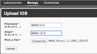
Now we need to add an image to use, I will be using an IOS 15 image I found, so again on the Manage tab, click on Manage IOSes. Firstly give it a name and an alias, then browse to the image and select it.
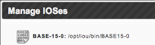
Then hit Upload. After a moment it will appear in the list of available images to use:
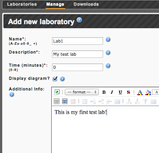
Click on the Laboratories and then click on the icon for Add New Lab on the icon menu on the right hand side.
Give it a suitable name and description, you can set it as a timed lab if you want (I am leaving it as 0 to say that there is no time set), whether to display the network diagram or not and any additional information.
Next we have to design the topology of the lab and this uses a NETMAP file, I am following the example given on the routereflector page.
A NETMAP file consists of a rows and each row contains an entry for where a link starts and where a link ends and includes the device ID. So to link device 10 to device 11 on ports 0/1 on each the line would look like:
10:0/1 11:0/1
So say we wanted to have two core routers (devices 10 and 11) connected to two WAN routers (devices 12 and 13) by a hub then we could do this:
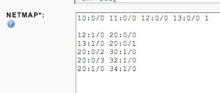
10:0/0 11:0/0 12:0/0 13:0/0 1
The 1 at the end signifies that the link type will be an IEEE 802.3 ethernet link. For a list of what you can do refer to this page: http://www.tcpdump.org/linktypes.html.
Now if we wanted to have the two WAN routers connected to three branch routers (devices 30, 32 and 34) via frame relay (device 20) we would do this:
12:1/0 20:0/0 107
13:1/0 20:0/1 107
20:0/2 30:1/0 107
20:0/3 32:1/0 107
20:1/0 34:1/0 107
The 107 specifies a Frame Relay link.
Our finished NETMAP now looks like this:
Now click on Add so we can start setting up out devices. The device setup looks like this at first, with our devices set for us as per the NETMAP file. Depending on what version you are on you may or may not see an entry for the hub.
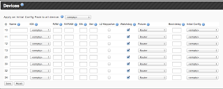
We start by naming our devices, and selecting the IOS for them to run, in the dropdown will be BASE-15-0, which is the alias we gave our uploaded image a little while ago. Then we can either set the RAM and NVRAM or we can take the system default.
The next two columns are important, these are how many Eth(ernet) and Ser(ial) portgroups there are. There are four ethernet ports per portgroup and four serial ports per portgroup. Ethernet portgroups are installed before serial portgroups – so a device with two ethernet portgroups and two serial portgroups will have the port layout of e0/0-3, e1/0-3, s2/0-3 and s3/0-3.
L2 keepalive is not supported on all IOSes (used to overcome the always-up ethernet interfaces) and Watchdog should be checked.
Lastly we can select an appropriate picture for the device, a boot delay if required and, if we have created one, an initial configuration that we can apply here.
The final configuration should look like this:
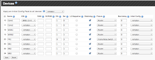
Once we click save we are taken to the main Laboratories tab and we can see our new lab. If we start the lab and look at the diagram we should see (after moving the devices around a bit, something like this: